PAINANI: A Six Legs Robot
Armando Chávez Plascencia, Jorge Romero Sánchez, Paola Sepúlveda Sánchez de la Barquera, Carlos Nava Jiménez, José Francisco Gómez Santoyo,
Humberto González Bravo, Alejandro Zavala Maldonado, Fernando Tellez de Urquijo, Irma Hernández Ballesteros, Fernando Tadeo Hernández Altamirano
&
Eduardo Gómez Ramírez
Laboratorio
de
Investigación
y Desarrollo de Tecnología Avanzada (LIDETEA)
UNIVERSIDAD LA SALLE
E-mail: egr@ci.ulsa.mx
Recibido: Junio de 2003. Aceptado: Julio de 2003
RESUMEN
En este artículo se presenta la descripción de todos los elementos mecánicos, eléctricos-electrónicos y de control del robot PAINANI. En este diseño
las innovaciones siguen siendo en la línea de bajo peso de la estructura y alta rigidez. Se utiliza un micro controlador de fácil programación para la
etapa de control. Se hicieron algunos cambios en la estructura para mejorar la rigidez debido a problemas de flexión del material anteriormente
utilizado que ocasionaba problemas en el control del paso.
Palabras clave: Mecánico, eléctrico, robot, painani, electrónico, control, micro controlador.
ABSTRACT
The Mechanical, Electrical–Electronic, and Control are the described parts/elements of the robot Painani. In this design the innovations still are
being the low weight of the structure and the high rigidity. A small and simple programmable micro controller is used. All this sections are described
in detail with figures and photos illustrating the explanation of every element. Some parts of the structure were rebuild because we needed more
rigidity, and the nylamid was over flexing the leg that caused errors to control the step.
Keywords: Mechanical, electrical, robot, painani, electronic, control, microcontroller.
 INTRODUCTION
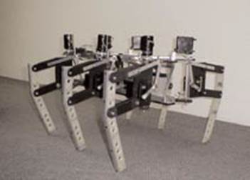
One of the most important results of the group GIDROM (Group of Development and Research in Mobile Robotics) is the robot that participated in the competition Walking Machine Challenge 2003. This year the design
was based on a six legs robot with two degrees of freedom for each one (See Fig. 1.a and 1.b).
Fig. 1.a Robot View (1st version)
 and required to add some materials to maintain more rigid the structure. The elements that will support the extremities were designed for them to have
a dynamic absorption. This was obtain- ed out of different thickness for the cover from the body and the base. In the body cover an alu- minum
structure was added to increase the Nylamid rigidity. It was placed in strategic points (Fig. 2). The aluminum structure was not placed in the base due
to the flexibility. The base
and required to add some materials to maintain more rigid the structure. The elements that will support the extremities were designed for them to have
a dynamic absorption. This was obtain- ed out of different thickness for the cover from the body and the base. In the body cover an alu- minum
structure was added to increase the Nylamid rigidity. It was placed in strategic points (Fig. 2). The aluminum structure was not placed in the base due
to the flexibility. The base
–made of Nylamid– needs to absorb the strong movements, hits and efforts.
Using the experience of the previous events a new version of the model is presented. May the sight be very similar, but the new elements re- present
the solutions of many problems pre- sented in the previous version.
ROBOT STRUCTURE
To describe all the elements of the robot the paper was divided in the following sections:
o Mechanical elements
o Electrical and Electronic elements o Control elements
In the following section the parts included in the mechanical elements will be described.
MECHANICAL ELEMENTS
The mechanical elements consist of the follo- wing parts:
1. Body
2. Extremities
3. Collector mechanism
Body
The body was designed in such a way that the structural resistance is different depending on the part that treats. For example, the inner struc- ture
was designed in order to be as rigid as pos- sible because it will be the supporting part for the robot’s feeding and control elements. That worked but
we still had errors in the movement
Also, to reduce the weight of the structure, it was combined with the extremities, meaning the axis of the legs was also used also as joint ele- ment
of the body (Fig.3).
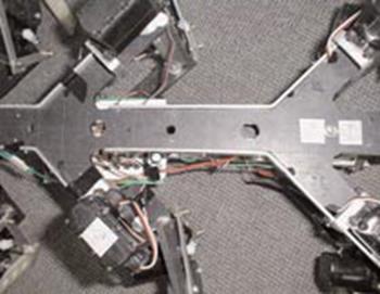
Fig. 2 Detail of the Robot Structure of Alu- minum and Nylamid
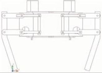
Fig. 3 Front View of the Robot
This double function of the axis reduces weight and keeps the rigidity required in the ex- tremities joints with the body. In that part we add
some aluminum that joined the upper boome- rang with the lower one to make the structure like a cage, keeping the same distance between the 2
boomerangs.
To reduce the friction, bearings were placed in each axis interlocked in the body. Also, to redu- ce weight, holes were made in different diame- ters
in the neutral fibers of the body. Fig. 2 shows these holes. The shape of the body, loo- king like 3 boomerangs joined by a board is to maximize the
angular movement (see Fig. 4 and 5).
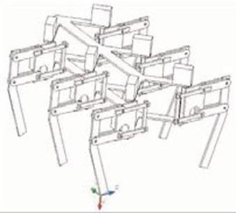
Fig. 4 Isometric View of the Robot
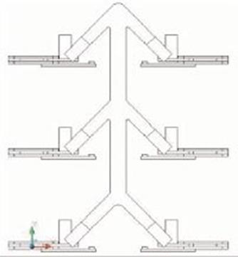
Fig. 5 Boomerang Shape
The extremities have two degrees of freedom for a suitable displacement of the robot (see Fig. 6). In the one degree of freedom, the servo used is
placed directly on the axis of rotation with alu- minum cylinders, but they were a little bit weak so we changed them for nylamid cylinders.
In the other degree of freedom a special sys- tem is included to transmit the torque from the motor.
Fig. 6 Extremities View
The Nylamid used is an auto lubricated one; this reduces the friction in the movement. The joints are made with brass, also to reduce the friction of
the movement.
We changed too the support of the Y–axis from Nylamid to Aluminum to make it less flexi- ble and avoid errors in the step.
All the screws and prisoners are easy to find and the same for all (1/8 for the screws and 5/32 for prisoners). Depending on the type of the joint
between the materials nuts of security or cord in the material were used; for example, in the joints Al–Nylamyd, we used prisoner and in the axis of
the motor with the first transmission we used element security nuts.
All the elements described in the previous sections allowed the weight of each extremity to be less than 1 kg.
The design of the extremity allows a variable step, depending on the angle of the servo. The maximum length of the step is 19 cm and a ri-
sing of 9 cm. This can only be modified increa- sing the length of the links showed on Fig. 7 and 8.
Fig. 7 Top View
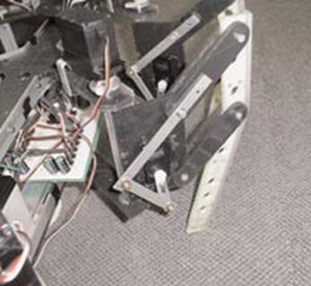
Fig. 8 Detail of the extremities (1st robot)
ELECTRIC AND ELECTRONIC ELEMENTS
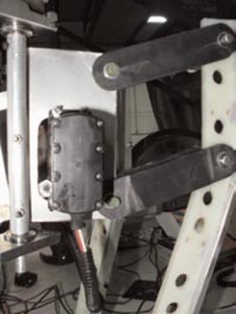
Fig. 9 The new leg
General Feeding
The feeding is 9 and 6 volts for the basic stamp and 6 volts for the dc servomotor. The servos are connected to the micro–controller with 12 kW pull
down resistors.
The new basic stamp characteristics
· 32 + 2 Dedicated Serial
This model gave us more memory, more pins and more commands making the control easier.
Automatic Emergency Stop System
A circuit that disables the grounds of all system elements was used; this way the robot switches off all its components until it is taken back manually
to its initial position.
Servomotors
The servomotors used are CIRRUS brand. The selected model is CS-650 FET, Mega Pro FET Ball
Bearing Servo with the next specifications: Size (in.) 2.48x2.43x1.26
Weight (oz) 5.80
Speed (sec/60_) 4.8 V– 0.19
6 V– 0.16
Torque (oz./inc) 4.6 V – 254
6 V – 309
We used one servo for each freedom degree, that is to say, two servos for each leg.
CONTROL ELEMENTS
The main control of the robot runs on a BASIC Stamp micro–controller [1]. The name is the result of the combination of the
programming languages PBASIC and Stamp. The Term Stamp is used because the size of the board is stamp size. The basic stamp has 16 input/output ports
and uses 5v.
The robot programming is made using an edi- tor and it is sent to the micro–controller via a serial port of a PC. 12 output ports and 4 input ports
were used to program the robot.
The servo control was designed generating periodic pulses similar to the one used by RC. This system is similar to the PWM, in order to reach the
desired position.
An example is presented immediately, where the movement of a servo, in a rank of 0° to 90°, is simulated. Considering the servo is in the 1000 (90°)
position, the program makes the servo reach the 500 (0°) position, and it returns later to the original position. The combination of pulseout and pause
commands creates the low and high state. This is necessary to generate the periodic pulse. This should be sent 100 times, for the servo to reach the
final position. At the beginning the x variable is declared to be 16 bits and the output is at a high normal state.
Example: x var word output 1
for i=1 to 100 pulseout 1,500
pause 1 next
for i=1 to 100
pulseout 1,1000
pause 1 next
In this project we only use an open loop con- trol, but with the same design it is possible to define the Micro–controller in a slave-master
configuration. The micro–controller will work like the slave and an on–board computer with Artifi- cial Vision algorithms or similar sensors can work
without change in the mechanical, electric and electronic elements.
Currently it is possible to control the robot in two ways: Using an RC (Fig. 10) or with a spe- cific program like the previous example. The
subroutines are synchronized with the RC in such way that the movements correspond to the following diagram (Fig. 11):
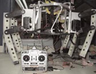
Fig. 10 The robot with the RC
Fig. 11 RC Diagram
Go Ahead.
In this movement the robot walks ahead using sequences that are called 3–3 or 2–2–2. 3–3 means that the robot uses 3 legs in every step, 2 in one side
and one in the other side. This sequence is very stable and quick. The speed depends of the angle used in the servo. The other sequence moves all the
legs to
walk and place facing each other, every time, one pair of legs.
Turn
Right.
This sequence uses a similar sche- me than 3–3 but every side moves in a different way making the robot turning around without displacement.
Turn left.
It is identical to the previous sequen- ce but to the other side.
Turn right walking.
The idea here is that the ro- bot can turn to some side but moving at the sa- me time. This is similar to go ahead but the movement of one leg (the middle
leg) is fixed. The result of this movement is making the robot circling in radius r. This radius depends on the angle defined in the servo.
Turn
left walking.
It is identical to the previous sequence but toward the other side.
Go back.
The sequence here is almost identical to go ahead but the displacement makes it to go back.
Go back slow.
The only difference in this se- quence is the angle of the servos. Here, we divi- de the angle by two, but it is possible to use other number to make the
movement slower.
Stand up.
This routine only puts the robot in one position to be ready for one movement.
In movement using programming, it is only necessary to send the previous commands with a specific number of steps.
CONTROL
In this version of the robot we introduce a new scheme of programming. We "edit" the mecha-
nism of movements to improve the speed, the movements’ precision, and the power consump- tion. We simulate the cinematic of the robot using the matlab
program to know how it is pos- sible to fulfill the previous condition.
We use a small high in the movements of the legs and it is possible to control the speed using different range of angles for every movement. In this case
we use only 3 speeds.
CONCLUSION
The major goal in this project was to follow the main principle of keeping it simple; in this new version we were also trying to keep the KISS principle.
Every step made during the building period improves the simplicity of the design, keeping the minimum elements to reach the main objective: to walk and
being autonomous.
The mechanical design improves the pre- vious ones increasing the rigidity of the robot and reducing the weight. In the electrical and electronic part our
design also keeps the sim- plicity, by combining the basic stamp. With this experience it is possible to construct a new robot in a very short period of
time and with a very low cost.
This robot won the Engineering Value award under the Walking Machine Challenge, 2003.
ACKNOWLEDGMENTS
We acknowledge all the support from the Labo- ratories of the Engineering School to develop this project and the support of the
Research Coordination.
REFERENCES
1. Parallax, Inc.
http://www.parallax.com/junio 2003.